|
Sparrow / NmG
Wiki |
Sparrow /
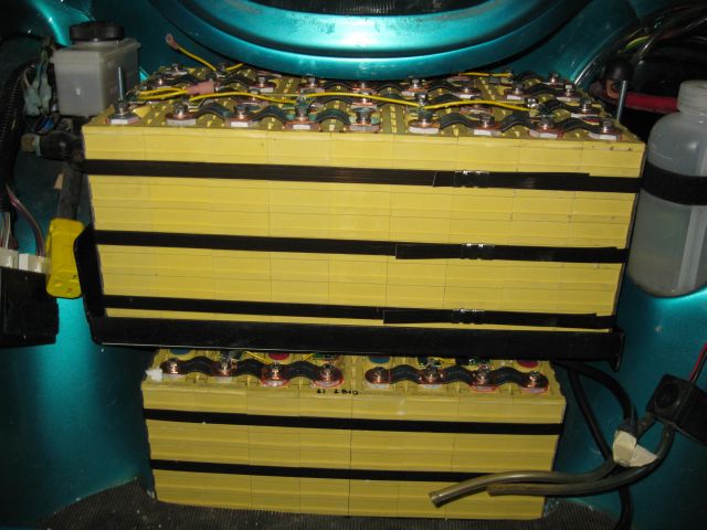
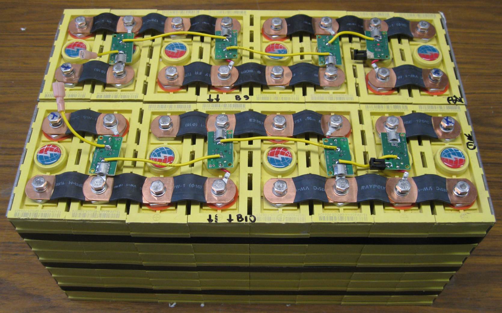
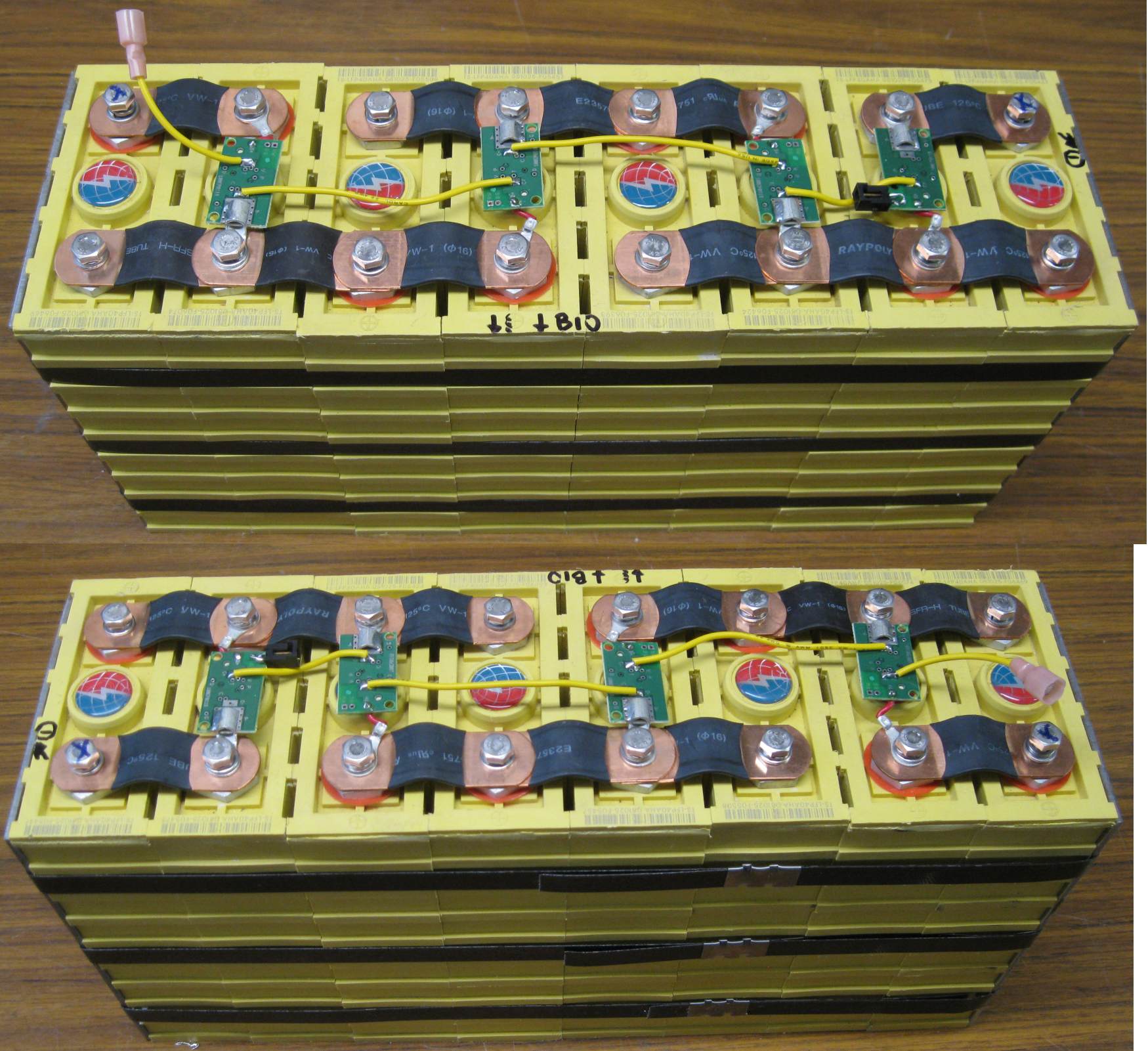
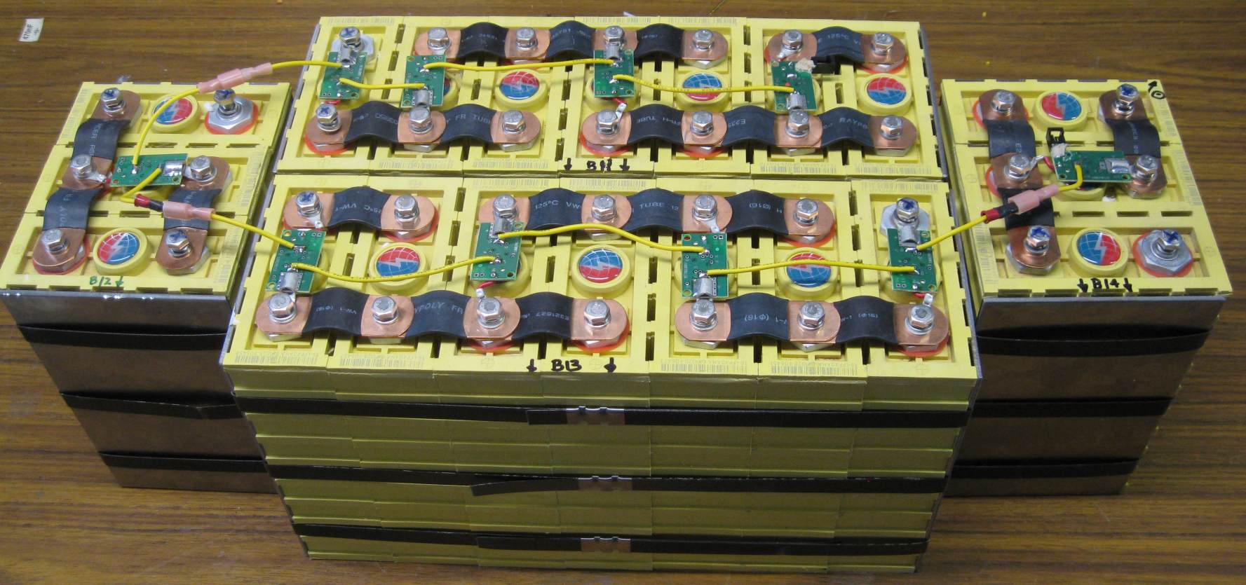
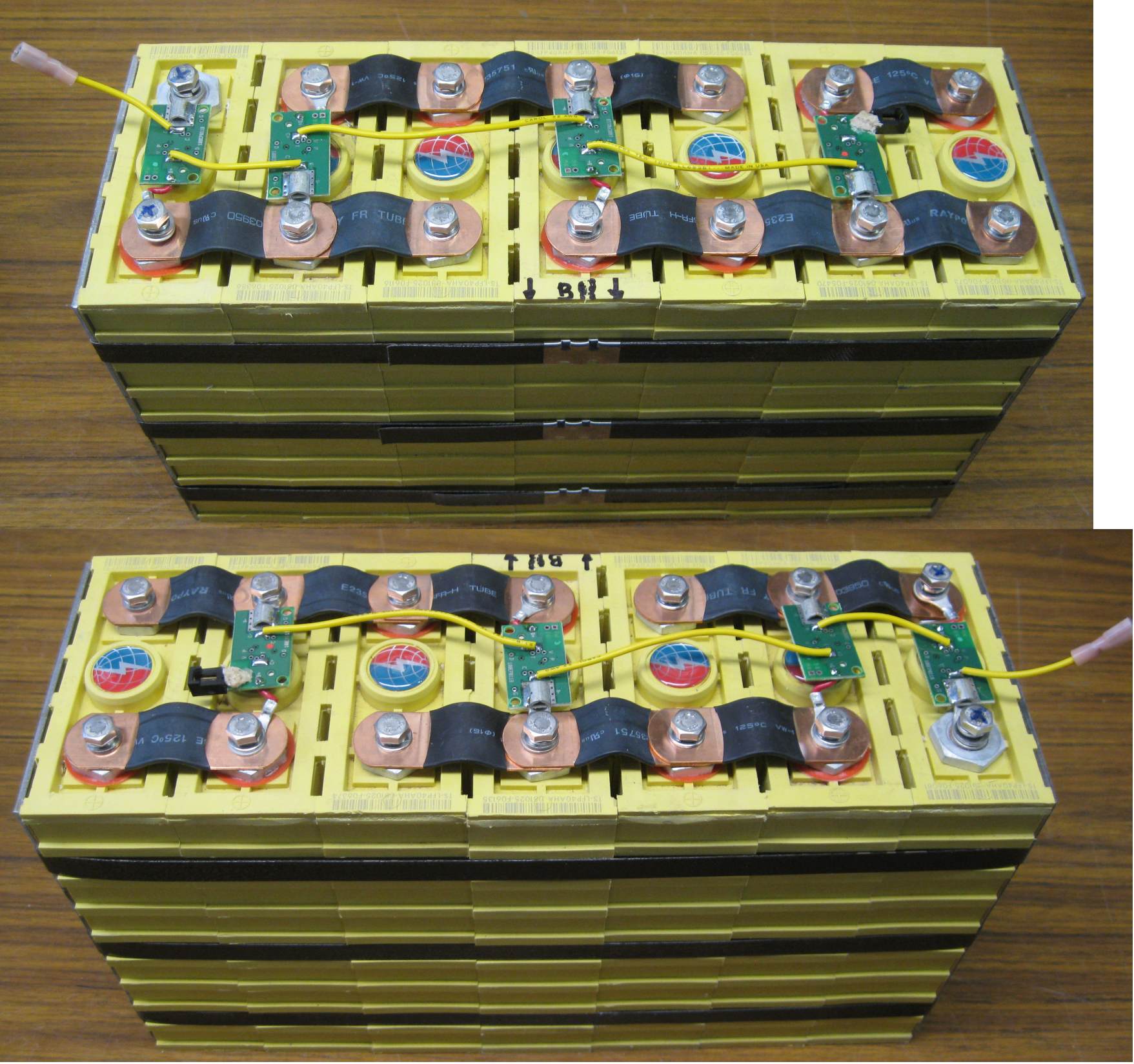
ElithionUnderHoodOn other pages Cell arrangement27 pairs From most positive to most negative: Batt Bank Cells Arrang Loca Placement 7 D 9 5S2P hood top-layer-front 8 D 9 4S2P hood top-layer-rear 9 F 8 4S2P hood bottom-layer-rear 10 F 8 4S2P hood bottom-layer-front 11 E 7 3.5S2P hood mid-layer-rear 12 E 3 1.5S2P hood mid-layer-right 13 E 7 3.5S2P hood mid-layer-front 14 E 3 1.5S2P hood mid-layer-right __ _ __ ______ 8 3 54 27S2P HOOD TOTAL Cell planningWe made mock-ups of the cells using foam panels (construction material used for insulation). Three batteries (from most positive to most negative)
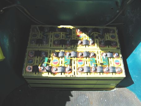
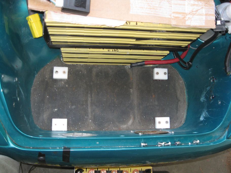
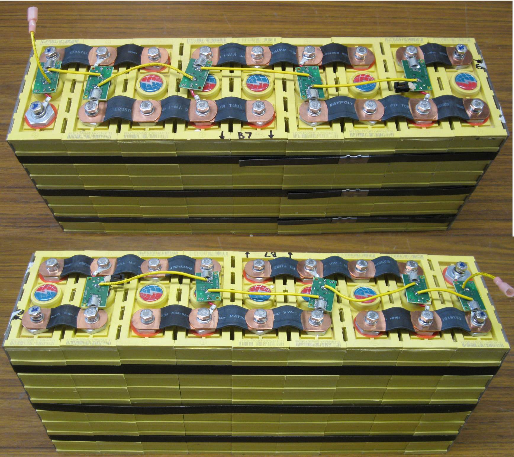
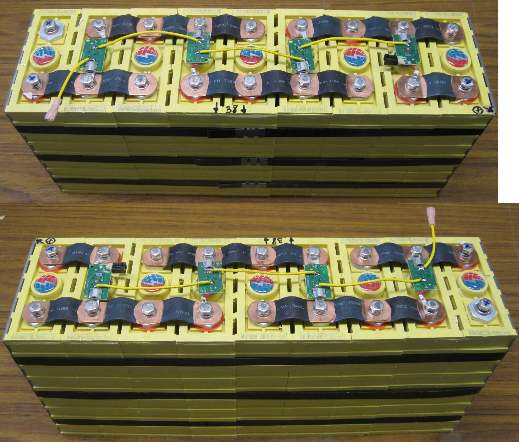
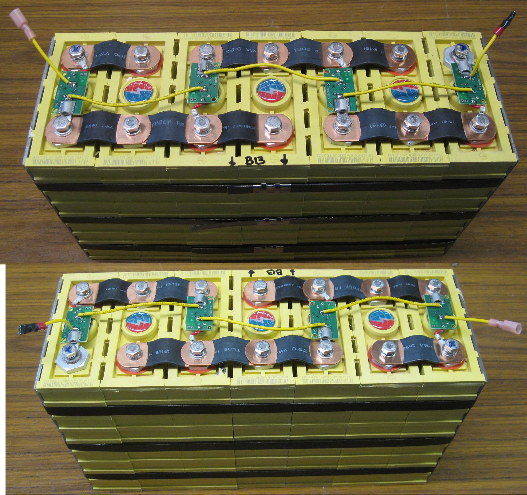
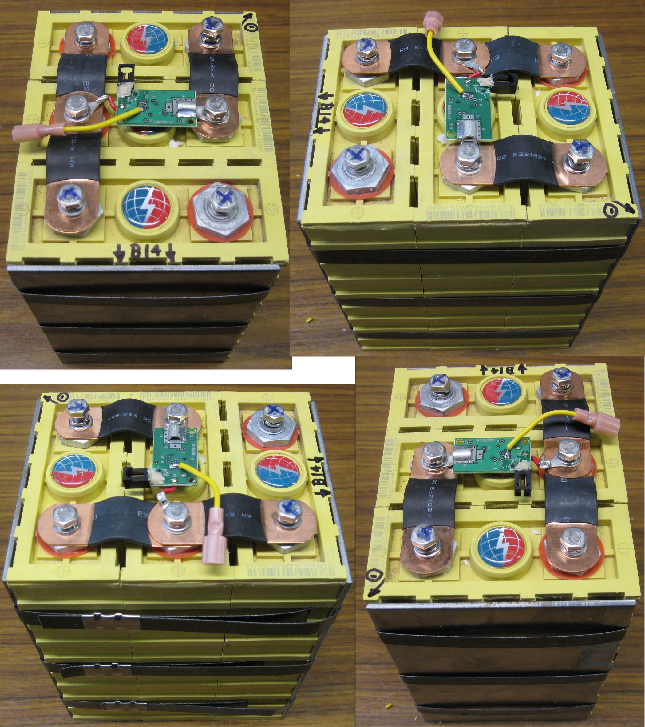
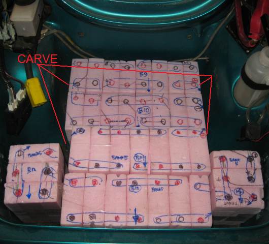 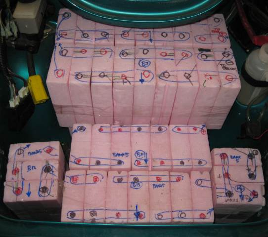 Mock-up, in place, without top-layer batteries (left) and with (right) 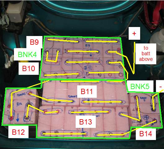 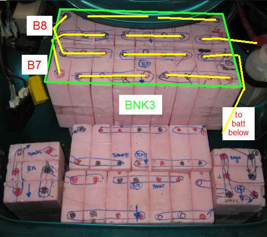 Battery and bank numbering, without top-layer batteries (left) and with (right) The bank numbering is wrong. Bank D is labeled "3", Bank E is labeled "5" and Bank F is labeled "4". Battery constructionBank D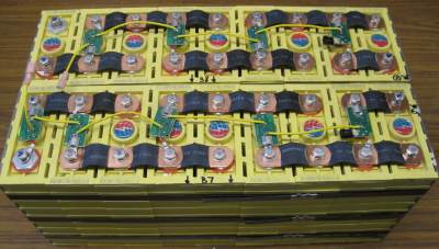 Bank D on the bench. Enlarge  Battery 7 Enlarge 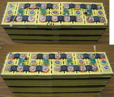 Battery 8 Enlarge Bank F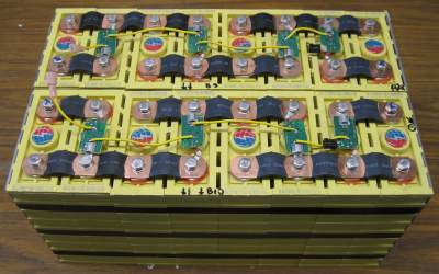 Bank F on the bench. Enlarge 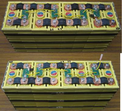 Battery 9 Enlarge  Battery 10 Enlarge Bank E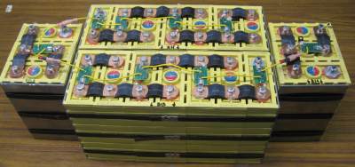 Bank E on the bench. Enlarge  Battery 11 Enlarge 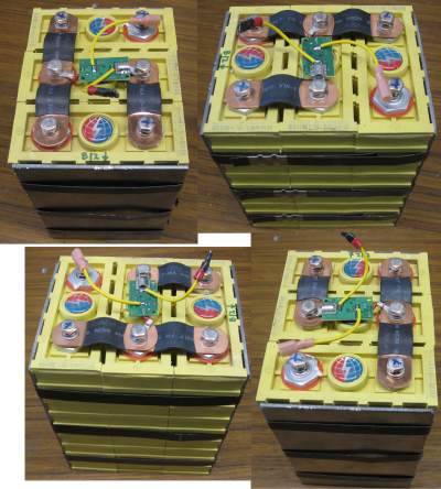 Battery 12 Enlarge  Battery 13 Enlarge  Battery 14 Enlarge Chassis carvingRemove the clear hose along the firewall. The corners in the lower compartment need to be carved out to allow for B10 and B11 to fit. 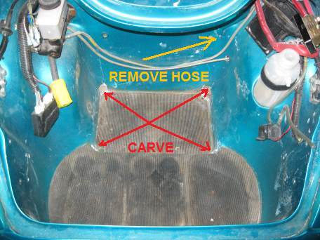 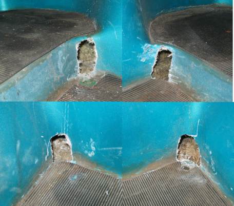 Four corners that need to be carved in lower compartment Make sure to remove any portion of the fiberglass frame that rises, which would keep the battery to sit down on the mat.   Holes filled with expanding foam, then cleaned up Battery fitting
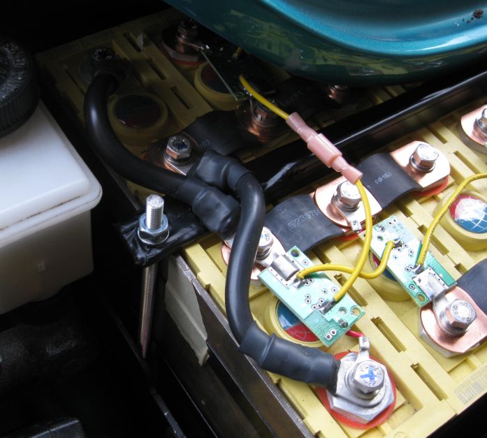
Cable prepPrepare 5 jumpers:
Rack mprepConvert the stock rack for the top Optima battery, to hold the Li-Ion battery instead  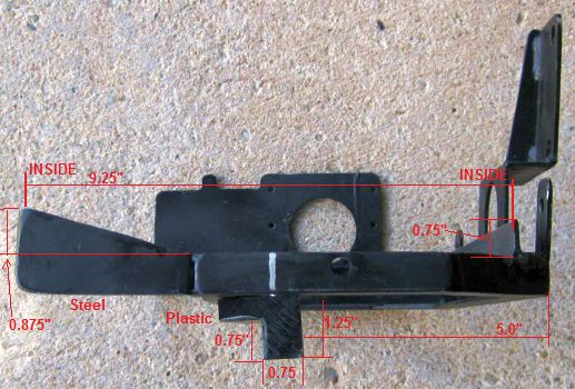 Rack, modified Battery installationBank F
  Bank F in place; connected Bank DBracketBuild a bracket to hold down bank D: a simple bar with 2 holes that will fit on the rods from the bottom of the rack. Isolate the bracket to avoid short circuits. Install
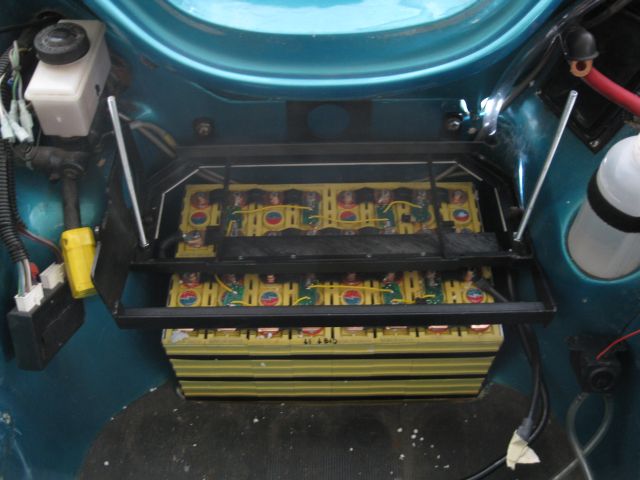 Rack in place
 Bank D in place
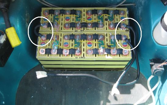
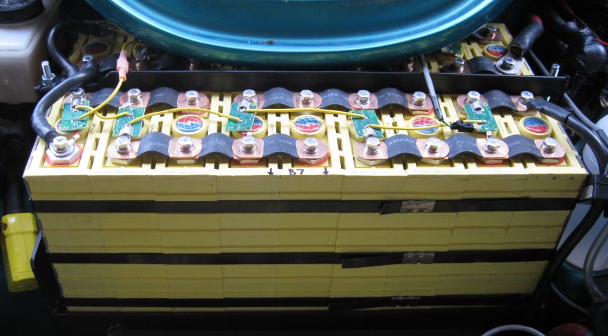  Bank D secured and connected Bank ERetaining blocks
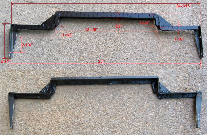
 BracketBuild a bracket to hold down Bank E.
 BatteriesInstall and connect the Bank E batteries 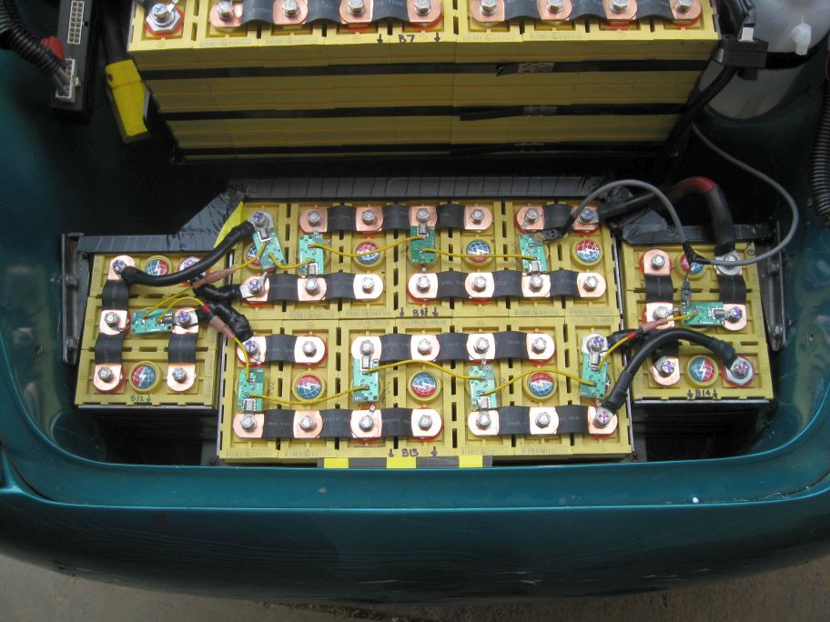 |