|
Sparrow / NmG
Wiki |
Sparrow /
LightsSparrow >> Service >> Electrical >> Lights IntroBrake Light switch installation.Photos are in the Yahoo sparrow_ev group photo section under Improvements-brake switch ver2. The switch is mounted to a bracket on the right end of the brake pedal assembly. The switch makes contact with the brake linkage bracket. I had to install new bolts that are 5/16 - 28 x 1 instead of the original 5/16-28 x 3/4. The switch was purchased from Advanced Auto parts for $2.99. Part number SLS62 made by BWD Automotive (made in USA). The bullet connectors were cut from the wires going to the pressure switch and a wire was added to the bundle of blk/wht (12V). The blue .157 bullet connectors are available at Advanced Auto, Pep Boys and Auto Zone. The power wires were reattached to the pressure switch. The new wire went to one side of the new switch. The two white wires were separated and a determination of which one went to the brake light. The one going to the computer was terminated and reattached to the pressure switch. The wire going to the brake light was spliced to the wire going to the new switch. The pressure system operates normally and now it only takes a small movement of the brake pedal to light the brake lights. The amount of movement needed is adjustable with the switch mounting. Headlight high beam / low beam foot switchFrom Russ: I ended up taking the old switch into a NAPA store and found that their part number DS115 was almost identical and it works fine. There are three contacts and by attaching the color coded wires up in the same relative positions as the old one was wired cause the high and low beams to cycle properly. Here are some things that will save you some time, but it is a pretty easy and straight forward operation. You will want to remove the steering column cover (5/32 allen wrench for the two fasteners near the top). Once it is removed, pull the forward edge of the carpeting toward the rear until the plastic tunnel is uncovered. You should be able to just lift the plastic tunnel that covers the switch out. The switch can be removed with a 10MM open end wrench on the two exposed nuts. (You can try a socket, but a socket is not likely to have enough room at one end to slip over the nut...to close to the switch body.)Depending on your clearance, you may have to resort to vise-grips or pliers. There is a U-shaped mounting bracket on the bottom side of the switch, and the two nuts go over the studs in the bracket so that the switch can be mounted to the round bar. My old switch had the end of one mounting hole cut out to make it easier to line up and turn the nut. You will want to cut this out of your new switch as well, or you will have a very tough time getting the nut to turn because the side of the switch is too close to the mounting hole. The other hole is somewhat elongated so it is easy to work with. A hacksaw does the job nicely. It is very soft metal. (You could probably pinch it off with a needle-nose pliers if you were careful.) The switch seems to have the best clearance by mounting it with the contacts on the right side. The plastic body of my switch was a little loose within the pot metal housing....it may have been deformed by over-tightening. When you position the switch, you will see that the bar is not consistently shaped...there is a taper to it. Mounting it too far to the right will cause pressure from under the plastic body when you tighten the mounting nuts. That may also be what caused mine to fail. 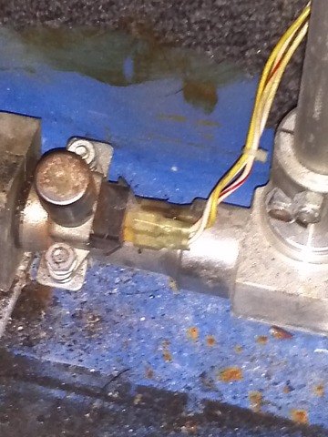 |