|
Sparrow / NmG
Wiki |
Sparrow /
DC-DCConverterSparrow >> Service >> Electrical >> DC-DC Converter IntroThe job of a DC to DC converter is to provide an isolated DC power supply driven from an existing DC power supply. The output voltage can and often is different from the input voltage. In this case, the input voltage is whatever the batteries in the Sparrow are currently sitting at (between 130V and 210V.) The output voltage is 13.2V. This gets used to run all the "12V" components in the Sparrow that are standard automotive parts, including the lights, the radio, the gauges, etc. The Sparrow came standard without a 12V accessory battery, relying on the DC-DC converter for all of its 12V needs. This decision has led to many failures, as the DC-DC converter used in a Sparrow can only supply 300W (or maybe in some, 400W) peak, and less when it gets hot. VicorThe DC-DC converter used in many Sparrows was the Vicor VI-M51-EQ (400W output) or VI-M51-ES (300W output.) In mine (#220) it was mounted on the motor controller heat sink. Information about it can be found at http://www.vicorpower.com/products/configurable/megamod/?expresscode=megamod. For easy reference, see the datasheet (Attach:ds_megamod.pdf) or the installation guide (Attach:ds_megamod_install.pdf). MountingCorbin mounted the DC-DC converter on the motor controller heat sink (at least for models with a Kilovac controller.) This wasn't such a great solution, as it doesn't adequately cool the Vicor. See one possible modification here: DC-DC Heat Sink Electrical analysisWe have take measurements of the current in and out of the Vicor DC-DC converter in use in the Sparrow.
Wiring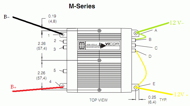 The B- (black) and B+ (red) wires from the battery pack power the DC-DC converter through contacts 1 and 4, respectively. The DC-DC powers the 12 V system wires (green for the common aka 12V-; yellow for the 12V+) through contacts E and A, respectively. Two wires are used to sense the 12 V voltage; the negative one (green) connects terminals A and B; the positive one (yellow) connects terminals E and D. |