|
Sparrow / NmG
Wiki |
Sparrow /
DefangingSparrow >> Service >> Modifications >> Defanging IntroMany Sparrows with KiloVac controller have the 12 V circuit connected to the high voltage circuit. This is very dangerous, and prone to major damage to the controller. Tghis was done so that the controller could measure the battery pack's voltage, and reduce the drive if that voltage was too low. It was a very bad solution, and now we have to deal with it. "Defanging" is the process of changing the circuit to disconnect the high voltage from the low voltage. What worked for me may not be the same for other Sparrows. My #237 is a pizza butt with a first generation Kilovac controller (contactors outside the controller). My DC to DC is mounted on the side of the Kilovac controller in the back right compartment. I had a jumper wire from the 156 volt (pack) ground to the 12 volt ground on the DC to DC. I also have an EVBC black box in the back and an EVCL black box in the front. If you do not have all these pieces parts the modification may be different. Defanging instructionsWiring modification
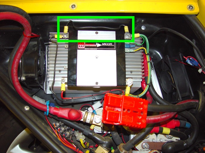
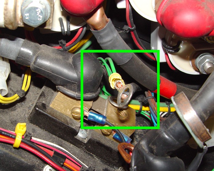
EVBC modification:The EVBC is the black box below the controller, the shunt and the DC-DC converter. See the orange wire on the rear most connector, this is the high voltage wire for the battery monitoring, this orange wire should be clipped flush on connector and trace back to it origin and removed entirely from the harness. You should find a fuse holder and wiring back to the main contactor. Remove all of this high voltage circuit. 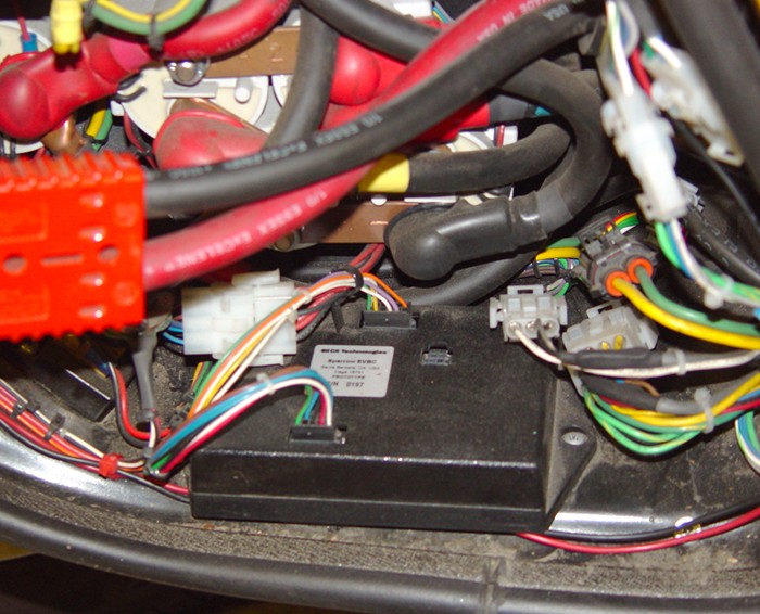 R24, R25, and R21 makes a voltage divider that is .0182 of the input voltage, so a 200 volt input will provide 3.64 volt to the processor chip.
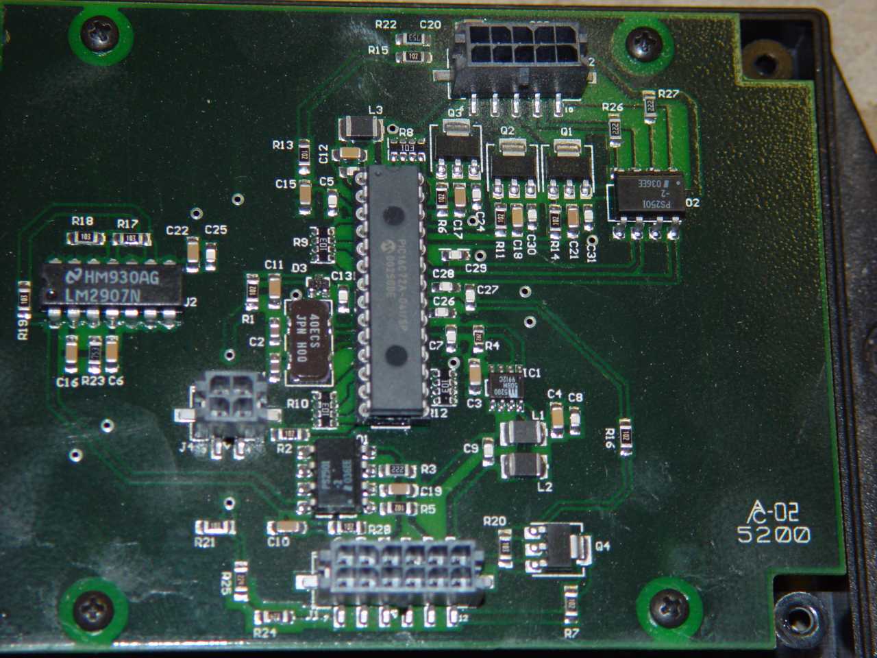 EVBC PCB Click to enlarge  EVBC PCB modification Click to enlarge Final
Better IsolationWhen the instructions above are followed, you end up with reasonable isolation between the 12V subsystem and the battery/motor/controller high-voltage subsystem. The two are joined, however, by a tiny isolation chip called the NTE1212 DC/DC converter which powers the Link-10, which shares a ground with the battery pack. You might consider installing a better DC/DC converter, one with better isolation properties, particularly if you're planning on installing a non-isolated charger like the Manzanita Micro PFC series. The following is a quote from Lee Hart, one of the people who's spent the most time trying to educate the electric vehicle building community. Jake Oshins <jakeo@windows.microsoft.com> wrote:
Sparrow... Corbin used a tiny 12VDC-to-12VDC converter to provide isolation between the 12V system and the Link-10 in the EVCL box... The part was an NTE1212. It can only handle 1W, but that's plenty. These are very cheap. They can also break (electrically). The more reliable parts that also fits the EVCL PCB is a Cosel DC-DC converter, these are much more reliable.
  Cheap, but not good.

  The Link 10 (aka E-meter) draws about 150ma at 12v in full
  sunlight (it brightens its display based on the ambient light
  level). 12v x 0.15a = 1.8 watts, which is a significant
  overload for a 1 watt DC/DC converter.  The input voltage
  range for the NTE1212 is 10.8-13.2v. This is inadequate;
  the accessory battery and its DC/DC converter can easily
  range from 10.5v to 15v.

  Most importantly, the input/output isolation for this part
  is wholly inadequate for an EV. The advertising claims
  1000vdc; but read the data sheet
  (at http://www.cd4power.com/data/power/ncl/kdc_ntec.pdf)!
  It says:
   voltage rating that can be applied across the part in
   normal operation?"
   ...less than 42.4 vac peak, or 60vdc... The part
   should never be used as an element of a safety isolation
   system... The NTE series has toroidal transformers, with
   no additional insulation between primary and secondary
   windings of enameled wire.
The DC/DC converter that you use to power a Link-10 / E-
meter needs *guaranteed* isolation sufficient to withstand your full pack voltage continuously. You aren't going to find this on a cheap DC/DC. The one Cruising Equipment used was a Datel part that cost over $30; but it was rated at 1500vac, UL listed, 9-19vdc input, and 12vdc at 0-250ma output. Or, you can use an AC/DC universal input, DC-output power supply to power the Link-10 / E-meter directly from your pack. Such supplies almost always have isolation voltage ratings of 1500v or more, and are UL listed (which means they have to GUARANTEE that it is isolated). For example, I am using an Astrodyne MSCC-5003 which has 3000vac isolation, 85-265vac (90-370vdc) input, 15v, 0-0.33a. This is a potted module with screw terminals that sells for $80, they have cheaper versions if you want to package it yourself. |